

.jpg)
.jpg)
.png)
.png)
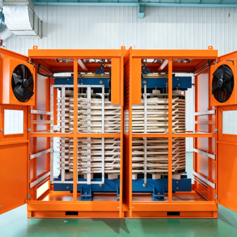





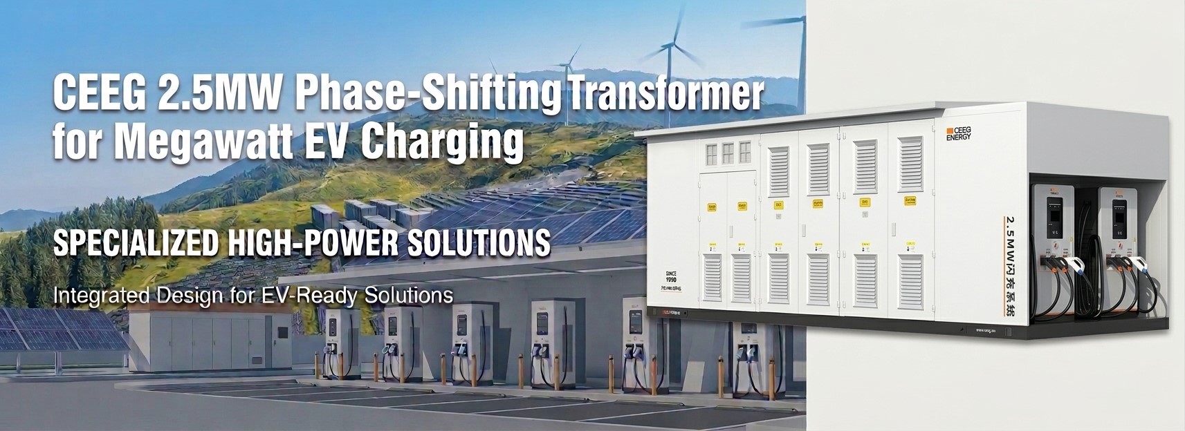
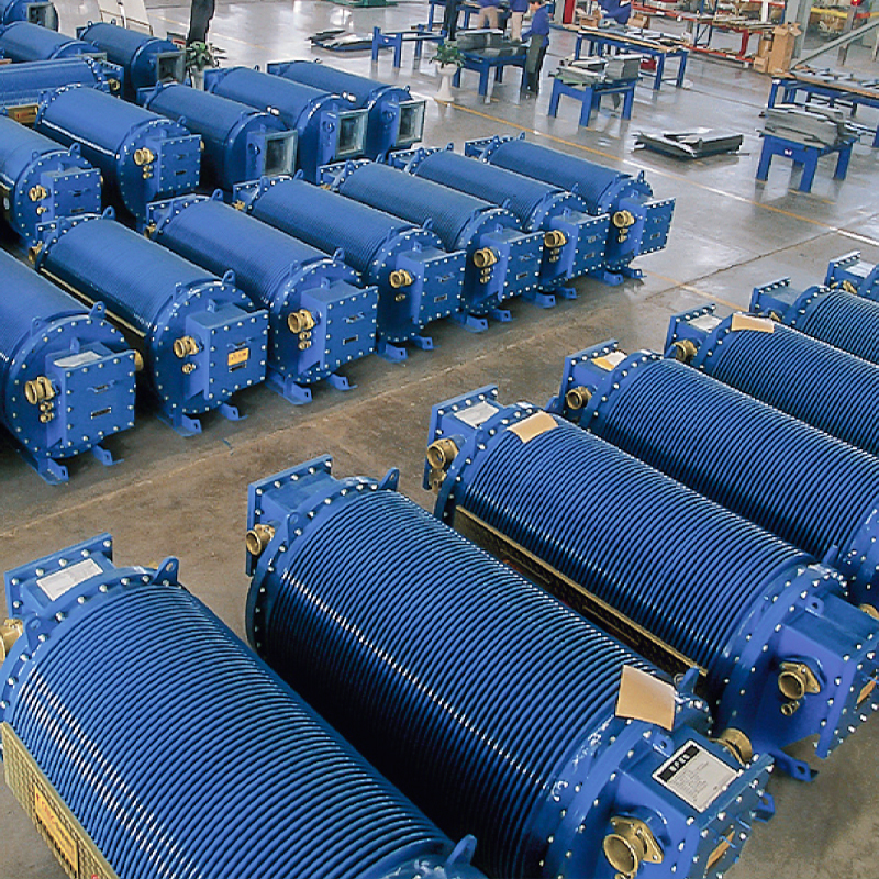
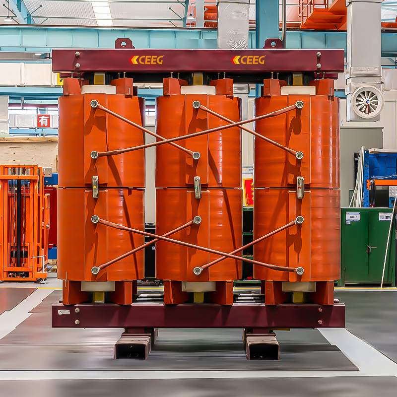
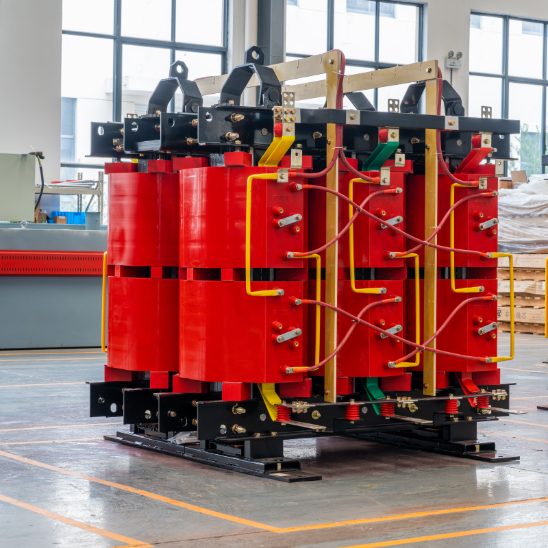
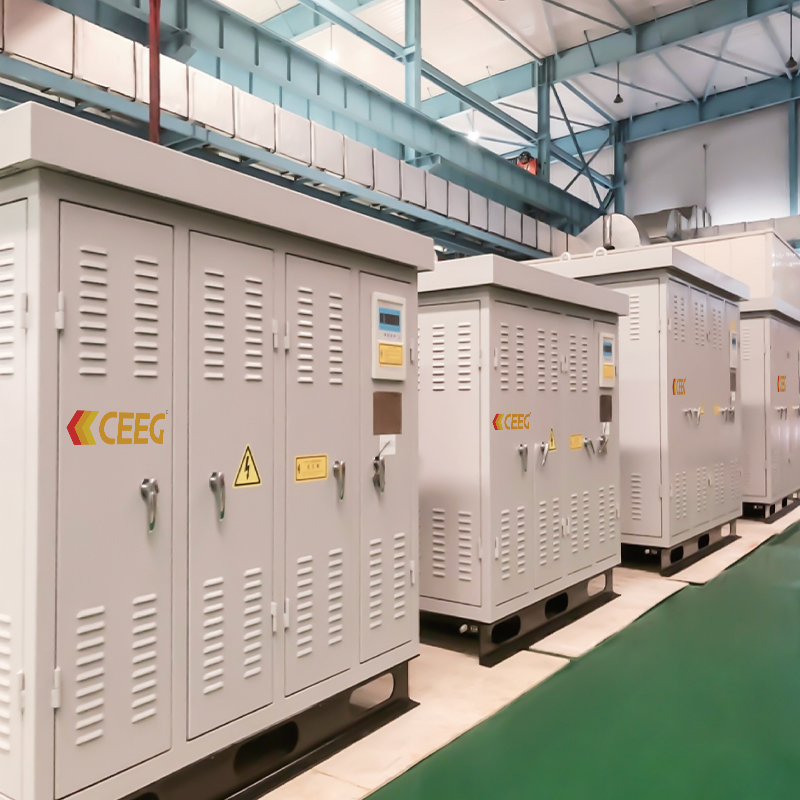
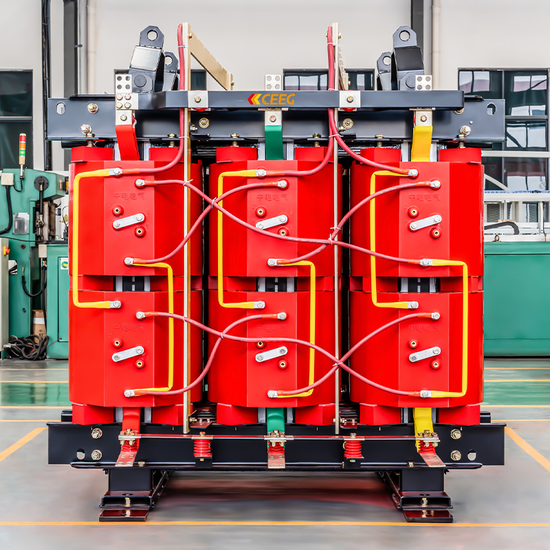
This is the transformer cabinet at the core of CEEG's 2.5MW megawatt charging system: a factory-built, skid-mounted unit that takes a 10kV medium-voltage feed and converts it into multiple low-voltage outputs with a phase shift built into the winding design. Those outputs then go on to the charging system's rectifier and DC-DC modules, but the transformer itself is what we supply and what this page is about.
It ships as a complete, pre-assembled cabinet rather than a bare transformer that needs to be wired into separate switchgear on site. Enclosure dimensions come in at 6500×3000×3000mm.
Charging stations at this power level generate a lot of harmonic distortion once you're running multiple rectifier modules in parallel. The usual fix is bolting on active or passive filtering equipment (APF or SVG) downstream, which is its own procurement line, its own footprint, and one more thing that can fail.
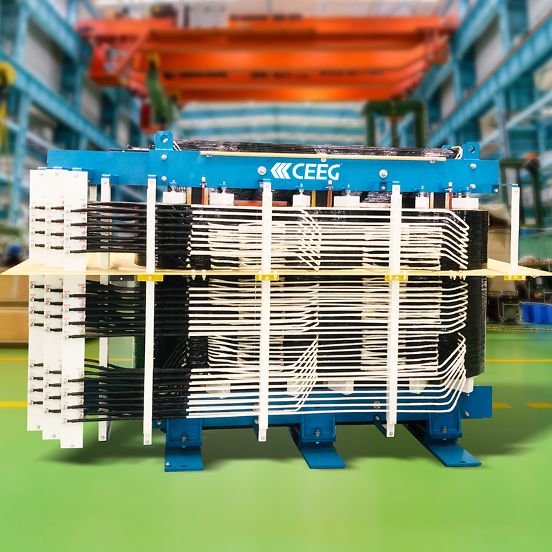
The phase-shifting design handles this differently. The secondary side is split into multiple winding sets, each offset from the others by a phase angle. When the resulting outputs get rectified, the harmonics from each set largely cancel each other out before they ever reach the grid. No separate filtering hardware needed. Based on our comparison against conventional low-voltage PFC architectures, this alone removes what's typically a 300,000 to 800,000 RMB equipment line for a comparable station.


On harmonics: No APF or SVG required. That's not just a cost line removed either; it's also one fewer subsystem to spec, install, and maintain over the life of the station.
On efficiency: Connecting directly at 10kV instead of stepping down to a low-voltage bus first gets full-load efficiency to 96.5% or above. Conventional multi-stage low-voltage transformer setups typically land at 93% to 94.5%. That two-to-three point gap sounds small until you're running a station 16 hours a day.
On footprint and install time: The unit comes pre-integrated from the factory, so there's a lot less on-site work: no low-voltage bus assembly, no separate switchgear installation, less cable and tray to run. Footprint comes in about 35% smaller than a comparable conventional setup. Install time typically drops from the usual month-plus timeline to 7-14 days.
On failure points: Downstream rectification in this architecture uses passive diode bridges instead of banks of active PFC modules. Fewer active components in the power path means fewer things to break. Over a 10-year horizon, our estimate puts maintenance cost at less than 40% of what a conventional low-voltage system runs over the same period.
On scaling up: Each secondary winding is electrically isolated from the others, so when multiple units are paralleled together, current sharing happens naturally. Conventional low-voltage multi-module clusters are known for circulating currents and uneven load sharing once they're scaled up, and that's usually where chronic reliability problems start. This design has been built out into configurations from 12 up to 96 charging paths without that issue showing up.
Applications this has actually been built for
Open-pit coal mining charging yards, where dust, vibration, and a weak local grid are standing conditions
Port and container terminal truck charging, where several trucks often need to charge at once in a tight footprint
Highway service area charging stations, where land cost and grid approval timelines push toward a compact, prefabricated build
Steel and coking plant charging installations running continuous, high-load operation
Shore-power and vessel fast-charging setups, where the direct medium-voltage connection suits the short window a ship has at berth